Overview
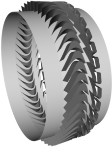
CRUNCH CFD was used to analyze and optimize a multi-stage turbine operating at Mach 2. The initial design had an issue of shock in the second-stage stator. CRUNCH CFD’s multi-module capability allowed us to to solve the problem in a simple fashion by breaking up the system into smaller components. We were able to resolve the initial design issue and optimize performance.
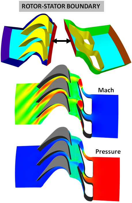
The rotor and nozzle sections were split into separate modules using different mesh topologies. The rotor module was solved in inertial frame while the rotor module was solved in rotational frame. During the CFD calculation, flow information is passed between the two modules at the rotor-stator boundary.
Rotor-Stator Boundary Features
| Mixing Plane |
|
| Frozen Rotor |
|
| Unsteady Rotor |
|
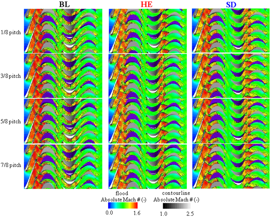
BL: Baseline case. Shock in 2nd stage stator.
HE: High Efficiency, same diameter as baseline. Shock eliminated and supersonic inflow into 2nd stage.
SD: Smaller Diameter but same efficiency as baseline. Shock eliminated again.